How to set up a LuminOx Optical Oxygen Sensor
Hi, today I want to speak to you about SST Sensing’s Optical Oxygen Sensor, which we call LuminOx.
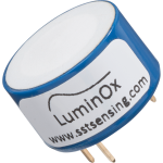
This is an example here.
We developed this sensor a few years ago because we believed there was a demand in the market for a non depleting and RoHs compliant sensor.
So the competition here is basically Galvanic and Electrochemical sensors.
Some of which contain harmful substances, such as lead.
They are still allowed to be sold, despite not being RoHs compliant but that can’t last forever because we can’t continue to make sensors with lead in them.
The other problem is that these sensors deplete over time, so they simply wear out a bit like a battery.
One of they other issues is that the more oxygen they see the faster they wear out, their lifetime is not really well known when you unpack one or buy one, you don’t really know how long it’s going to last. Because you don’t know necessarily know what environment it is going to be in, in terms of the amount of oxygen.
So we developed the LuminOx Optical Oxygen Sensor and it is based on optical florescence quenching.
So inside here, we have got a blue LED which emits pulses of high energy blue light. That blue lights hits a florescent material, which fluoresces and gives off an orange light.
Now the amount of light that it produces then decays over time.. and it decays over a short time. Of the order of a few microseconds.
And, in the presence of high oxygen concentration then the decay rates pretty fast and in the presence of low oxygen concentration then it is slower.
The microcontroller on board measure the time it takes for that waveform to decay, compensates for temperature and then provides an oxygen value based on that.
We calibrate every single sensor in the factory here at SST.
So the sensor, unlike electrochemical and galvanic sensors which have 3 pins and take no power.
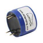
This sensor does need power, it needs a 5 Volt supply on these 2 pins. Then these 2 pins, the comms pins.
So rather than producing an analogue output which needs to be signalled conditioned and amplified, temperature compensated.
This sensor has a fully compensated, fully calibrated output. And we communicate the oxygen value via these 2 pins.
We choose to make it a RS232 TTL level compatible interface as it is a very simple way to connect to a microcontroller just through the micro’s UART.
So, 5 Volt goes to these 2 pins 3.3 Volt nominally TTL signal straight into your microcontroller. That’s 5 Volts tolerant but most microcontrollers are 3.3V.
Unlike other sensors of a similar style and size you don’t need any external circuitry. Just your microcontroller, and every product has a microcontroller these days.
So really eliminating the cost of additional circuitry.
I have got an example one here connect up and have just simply connected it to a USB interface, a USB to RS232 interface.
And I am recording my screen so you will be able to see that in a window when you watch this video. I am just going to apply power to it.
You can see it is starting to produce Oxygen values, so it is saying 20.67 which is pretty good. It is typically 20.7% oxygen in most normal indoor environments.
Not 20.95, 20.95 or the 21% that most people think of. The oxygen content on air, that’s based on the air being dry, of course there is some humidity so that oxygen value gets diluted a bit. So 20.7 is pretty typical, we’re measuring 20.6 something.
You see on the screen we have got, over here we have got the oxygen pressure in milibar. So up here it is saying 208.4 mBar, the temperature inside the sensor is 25°C, the barometric pressure, because there is pressure sensor inside, is 1009 mBar.
We use that pressure value and the oxygen pressure to calculate the oxygen concentration, here we are seeing it is 20.62.
You can see the bottom going down a bit, probably because I am breathing a bit of CO2 onto it.
I’ll put a lot more CO2 onto it now.
So you can see the oxygen has dropped now to below 19.5% and its going to keep on going, then it start to rise up again now that fresh air is drifting back into the sensor.
The gas gets in through this porous PTFE Hydrophobic membrane which keeps stuff out of the sensor, particularly moisture and dust.
That has a relatively slow response time because of that and of course I was just breathing gently, but if you were to direct the gas on there at a higher flow-rate, then the response time would be faster.
That’s the standard sensor. I’ll just let that carry on running.
We have got some other sensors here, so when we launched the product, we launched with this product, which is the standard one.
So the gas can enter through the front face but it can also get in through the gap between the case and the cover because that is not a gas tight seal. That’s fine for many applications where you just want to measure the oxygen concentration in the environment around the sensor.
We also have released this one, which is called the -S version and that’s a -X Suffix. And it is fully sealed at the back with epoxy. That means the only way the gas can get in is through the filter at the front. That means you can use it in an application where it was sealed here, you have the gas of interest on this side and you can have some other gas, like fresh air for example, outside the sensing area. If you used the original sensor for that the you would end up with a mixture of the gases inside and you would get an incorrect reading, It wouldn’t be measuring what you want to be measuring.
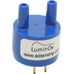
And finally we have recently launched this version, the -F version, F for flow-through. It has got in inlet port and an outlet port, it is also sealed at the back and is designed to go into instruments where you might have an inlet port and an outlet port and you would have a pump, pumping the gas through.
Something to be aware of, is that there is no filtration in this one, so it is up to you to make sure the gas is clean and dry before it goes in here.
You will get a significantly faster response time with this because you are flowing gas right into the sensor and across the sensing membrane rather than letting it diffuse through the PTFE filter.
A number of our customer have connected these to things like Arduinos and that works very well, obviously if you are making your own electronic circuit then it is much easier just to go straight into your microcontroller.
And, finally we offer this board called a LOX-EVB for LuminOx Evaluation Board. The idea here is that we have got a board where it is really for customers who don’t want to write their own software and they don’t want to produce their own PCB to start with. You stick the sensor on the board, you give it a 5V supply and it gives you 3 outputs. It gives you an industrial 232 Output so you can talk directly to a PLC say, that’s got an RS232 interface or any kind of industrial RS232 interface rather than a TTL one that I am demonstrating on my laptop. It’s also got an RS485 industrial interface. And finally, it’s got an analogue output.
So a very simple 0 – 5 Volt signal, representing 0 – 25% Oxygen. So, a very quick way to test the sensor and make sure it does what it wants you to do. Customers would typically design their own circuity because as I said, all it needs is 2 pins, the 2 UART pins and a micro. So, it really couldn’t be simpler.
That’s all I’ve got to say about the LuminOx Optical Oxygen Sensor. If you have any questions then please send them to technical@sstsensing.com and you can buy these sensors direct from us or from a number of our distributors. Thank you.


